

Первоисточник:
Publication Part No.LRL 0003ENG - 2nd Edition |
||
| |
Скачать | |
Далее идет результат тупого сканирования в html.
Есть результат чужого перевода
II MO HttdgescbafceMt vetteelSngsbdt leriiiebttdboek
R380 Boite de vitems nanveBe Mom el de review*
R3S0 Sdidtgetriebe UberbolwigKwerhwg
R380 Cenbio »«ca*ko Mawded revi»c*e
R3M Cafo de <obUo* monval Memd de rev mo*
R380 Caixo de veloddodes maid Mowdde rtvitoo
R380
MANUAL GEARBOX
R380
GEARBOX
OVERHAUL
MANUAL
This Overhaul Manual contains information applicable to the following models:
New Range Rover
Range Rover Classic 1995 Models on Discovery 1995 Models on Defender 1995 Models on
Publication Part No.LRL 0003ENG - 2nd Edition Published by Rover Technical Communication © 1996 Rover Group Limited

INTRODUCTION


INTRODUCTION
How to use this manual
To assist in the use of this manual the section title is given at the top and the relevant sub - section is given at the bottom of each page.
This manual contains procedures for overhaul of the R380 gearbox on the bench with the clutch and, if applicable, the transfer box removed. For all other information regarding Adjustments, Removal of oil seals, clutch, transfer box and gearbox unit, consult the appropriate Repair Manual for the model concerned.
This manual is divided into 5 sections, Data, Torque Settings, Service Tools, Description and finally, Overhaul.To assist filing of revised information each sub - section is numbered from page 1.
The individual overhaul items are to be followed in the sequence in which they appear. Items numbered in the illustrations are referred to in the text.
Overhaul operations include reference to Service Tool numbers and the associated illustration depicts the tool in use. Operations also include reference to wear limits, relevant data, torque figures, and specialist information and useful assembly details.
WARNINGS, CAUTIONS and Notes have the following meanings:
A WARNING: Procedures which must be followed precisely to avoid the possibility of injury.
CAUTION: Calls attention to procedures which must be followed to avoid damage to components.
NOTE: Gives helpful information.
References
Operations covered in this manual do not include reference to testing the vehicle after repair. It is essential that work is inspected and tested after completion and if necessary, a road test of the vehicle is carried out, particularly where safety related items are concerned.
Dimensions
The dimensions quoted are to design engineering specification with Service Limits where applicable.
REPAIRS AND REPLACEMENTS
When replacement parts are required it is essential that only Rover/Land Rover recommended parts are used.
Attention is particularly drawn to the following points concerning repairs and the fitting of replacement parts and accessories.
Safety features embodied in the car may be impaired if other than Rover/Land Rover recommended parts are fitted. In certain territories, legislation prohibits the fitting of parts not to the manufacturer’s specification.
Torque wrench setting figures given in this Manual must be used. Locking devices, where specified, must be fitted. If the efficiency of a locking device is impaired during removal it must be renewed.
The Terms of the vehicle Warranty may be invalidated by the fitting of other than Rover/Land Rover recommended parts. All Rover/Land Rover recommended parts have the full backing of the vehicle Warranty.
Rover/Land Rover Dealers are obliged to supply only recommended parts.
1
INTRODUCTION
SPECIFICATION
Rover/Land Rover are constantly seeking to improve the specification, design and production of their vehicles and alterations take place accordingly. While every effort has been made to ensure the accuracy of this Manual, it should not be regarded as an infallible guide to current specifications of any particular component or vehicle.
This Manual does not constitute an offer for sale of any particular component or vehicle. Rover/Land Rover Dealers are not agents of Rover/Land Rover and have no authority to bind the manufacturer by any expressed or implied undertaking or representation.
GEARBOX IDENTIFICATION
The procedures given in this manual cover overhaul of the R380 gearbox fitted to a range of vehicles and as such, certain differences exist between gearboxes, particularly in respect of the extension housings, gear change housings and transfer box selector housings. It is important therefore that before starting work, the gearbox to be overhauled is correctly identified. Identification can be made by noting the gearbox serial number prefix stamped on the RH side of the gearbox casing and referring to the following table which lists four types of gearbox, A, B, C and D together with their appropriate serial number prefixes.
^ NOTE: The gearbox types listed are only / \ intended as an aid to identification and do not relate to gearbox part numbers or a particular vehicle.
Overhaul operations in this manual list the applicable gearbox type referred to and it is important that the relevant operation is followed.
Type A gearbox prefixes: - 50A; 51A; 56A; 58A;
60A; 61A;
Type B gearbox prefixes: - 53A; 55A; 63A
Type C gearbox prefix: - 18A
Type D gearbox prefixes: - 64A; 65A
2

GENERAL DATA
Baulk ring clearances
1st gear end float
2nd gear end float
3rd gear end float
Adjust 5th - reverse hub - shim to -
Reverse gear idler shaft clearance
Mainshaft end float
Layshaft end float
Lubricants
Capacities
Sealants
NEW SERVICE LIMIT
0.5 mm (0.02 in)
0.05 - 0.20 mm
(0.002 - 0.008 in) 0.04 - 0.21 mm (0.0016-0.0083 in) 0.11 - 0.21 mm (0.004 - 0.0083 in) 0.005 - 0.055 mm (0.002 - 0.022 in)
0.327 mm (0.013 in) 0.337 mm (0.13 in) 0.337 mm (0.13 in) 0.055 mm (0.022 in)
0.04 - 0.38 mm
(0.0016-0.015 in) 0.38 mm (0.015 in)
0.01 - 0.06 mm
(0.0004 - 0.0024in) 0.06 mm (0.0024 in)
0.01 - 0.06 mm
(0.0004 to 0.0024 in) 0.06 mm (0.0024 in)
ATF M2C33 F or G Oil cooler fitted = 3.4 litres Non oil cooler type = 2.9 litres Joint faces - Hylosil RTV 102 Available through Unipart
Bolts and filler plug - Loctite 270 or Marston Bentley Hylogrip 640 (studlock)

TORQUE WRENCH SETTINGS
Oil pump to extension case 6 Nm
Attachment plate to gearcase 8 Nm
Attachment plate to remote housing 8 Nm
Bottom cover to clutch housing 8 Nm
Clip to clutch release lever 8 Nm
Cover to gear change housing 8 Nm
Spool retainer to gear case 8 Nm
Torsion spring locknut - adjusting screw 8 Nm
Screw - gear lever retention 8 Nm
Gear lever retainer bolt 15 Nm
Transfer box to remote housing bolts 25 Nm
Bias adjustment plate bolts 25 Nm
Selector quadrant setscrew 25 Nm
Gear change lever yoke setscrew 25 Nm
Adjustment plate to gear change housing 25 Nm
Extension case to gear case 25 Nm
Front cover to gear case 25 Nm
Gear change housing to extension case 25 Nm
Gear lever housing to remote housing 25 Nm
Guide - clutch release sleeve to bell housing 25 Nm
Pivot clutch lever to bell housing 25 Nm
Pivot plate to bell housing 25 Nm
Plug - detent ball and spring 25 Nm
Plunger housing to gear change housing 25 Nm
Remote selector housing to extension case 25 Nm
Slave cylinder to clutch housing 25 Nm
Upper gear lever assembly to lower gear lever 25 Nm
Clutch housing to gearbox 72 Nm
5th gear layshaft stake nut 220 Nm
SERVICE TOOLS
NOTE: Where the use of special tools is specified, only these tools should be used to avoid the possibility of personal injury and or damage to components.
|
Land Rover Number |
Rover Number |
Description |
|
LRT-37-001 |
18G47BA |
Adaptor input shaft bearing |
|
LRT-37-002 |
18G47BAX |
Conversion kit |
|
LRT-37-004 |
18G284AAH |
Adaptor for input shaft pilot bearing track |
|
LRT-37-009 |
18G705 |
Puller, bearing and oil seal collar remover |
|
LRT-37-010 |
18G705-1A |
Adaptor for mainshaft oil seal collar |
|
LRT-37-014 |
18G1422 |
Mainshaft rear oil seal replacer |
|
LRT-37-015 |
18G1431 |
Mainshaft rear support bearing track and oil seal collar replacer. |
|
LRT-37-021 |
- |
Adaptor for mainshaft rear support bearing track and oil seal collar replacer. |
|
LRT-37-022 |
- |
Adaptor for layshaft bearings |
|
LRT-37-023 |
- |
Layshaft holding tool |
|
LRT-37-024 |
- |
Rear mainshaft bearing track remover |
|
LRT-51-003 |
18G1205 |
Flange holder |
|
LRT-99-002 |
M547 |
Hand press |
|
LRT-99-004 |
18G284 |
Impulse extractor |
Service tools must be obtained direct from the manufacturers: V.L.Churchill,
P.O. Box No. 3,
London Road,
Daventry,
Northants, NN11.4NF England
1
SERVICE TOOLS

DESCRIPTION
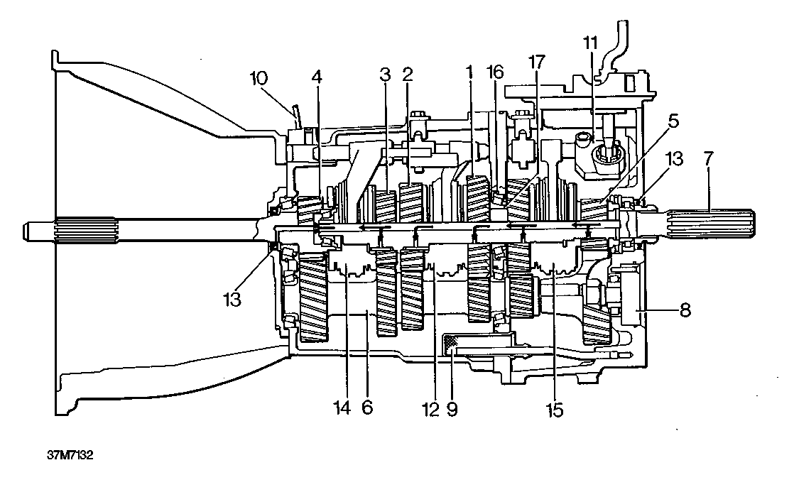
The R380 5 speed all synchromesh gearbox comprises an input shaft, output shaft, layshaft and reverse idler shaft.
Gearbox casings consist of a front cover, gearcase, centre plate and extension housing, all casings are located by dowels and sealed.
Selector forks for 1st/2nd and 3rd/4th gears are located on a single selector shaft inside the main gearcase whilst the selector fork for fifth and reverse gear is located on the same selector shaft inside the extension housing.
The input shaft, output shaft and layshaft are supported by taper roller bearings with all gears running on caged needle roller bearings. Output shaft and layshaft bearings end float is controlled by selective thrust washers located in the centre plate.
Lubrication is by an oil pump located in the extension housing which directs oil via internal drillings in the output shaft to lubricate the components.
|
1. |
Mainshaft 1st gear |
10. |
|
2. |
Mainshaft 2nd gear |
11. |
|
3. |
Mainshaft 3rd gear |
12. |
|
4. |
Primary input shaft/4th gear |
13. |
|
5. |
Mainshaft 5th gear |
14. |
|
6. |
Layshaft |
15. |
|
7. |
Mainshaft |
16. |
|
8. 9. |
Lubrication pump Oil filter |
17. |
Breather
Single rail gear shift 1st/2nd synchromesh Oil seals
3rd/4th gear synchromesh 5th/reverse gear synchromesh Selective spacers (mainshaft & layshaft end float)
Selective spacer (5th gear/reverse hub) 12/96
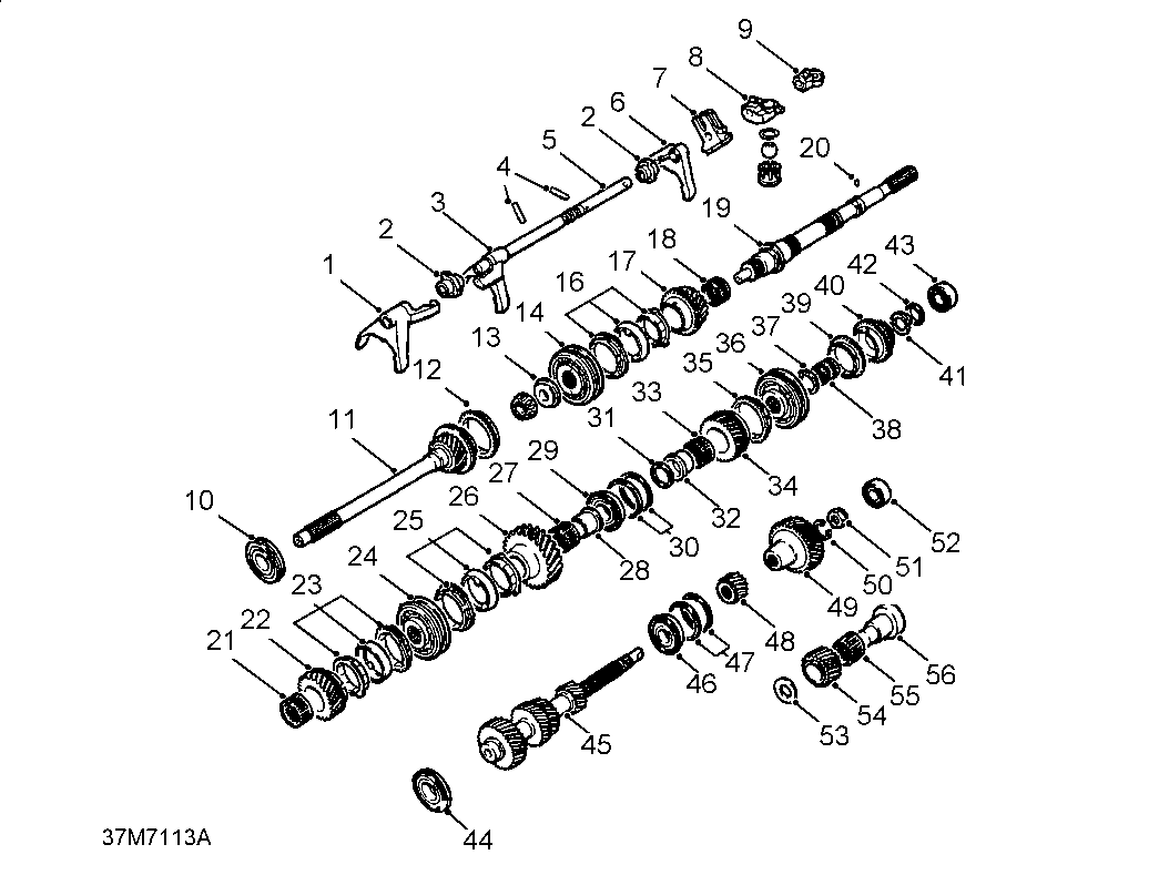

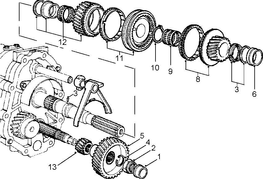
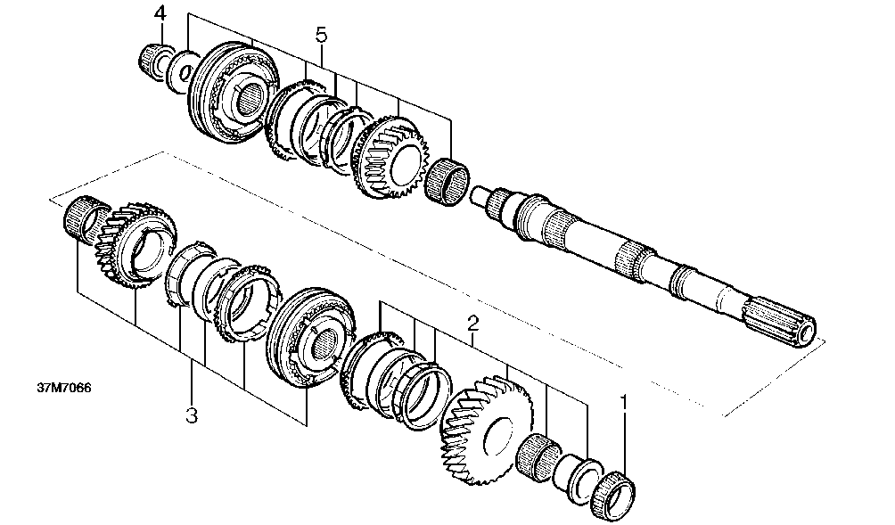
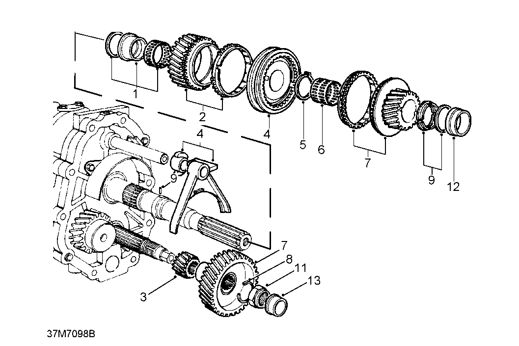
GEARBOX COMPONENTS - GEARS AND SHAFTS
1. 3rd/4th gear selector fork
2. Interlock spool
3. 1st/2nd gear selector fork
4. Selector shaft yoke pins
5. Selector shaft
6. Reverse/5th gear selector fork
7. Selector quadrant - Type A gearbox
8. Selector yoke - Type B/D gearbox
9. Selector yoke - Type C gearbox
10. Input shaft front taper bearing
11. Input shaft
12. 4th gear synchro ring
13. Pilot taper bearing
14. Spacer
15. 3rd/4th gear synchro hub and sleeve
16. 3rd gear synchro rings
17. 3rd gear
18. Needle roller bearings
19. Mainshaft (output shaft)
20. Roll pin
21. Needle bearing
22. 2nd gear
23. 2nd gear synchro rings
24. 2nd/1st gear synchro hub and sleeve
25. 1st gear synchro rings
26. 1st gear
27. Needle roller bearing
28. Bush
29. Mainshaft taper bearing
30. Selectable shims
31. Selectable washer
32. Bush
33. Needle roller bearing
34. Reverse gear
35. Reverse gear synchro ring
36. Reverse/5th gear synchro hub and sleeve
37. Circlip
38. Needle roller bearings
39. 5th gear synchro ring
40. 5th gear
41. 5th gear segments
42. 5th gear segment retaining ring
43. Mainshaft rear support bearing
44. Layshaft support bearing
45. Layshaft
46. Layshaft support bearing
47. Selectable shims
48. Layshaft reverse gear
49. Layshaft 5th gear
50. Split washer - later gearboxes
51. 5th gear nut
52. Layshaft rear support bearing
53. Spacer
54. Reverse idler gear
55. Needle roller bearing
56. Reverse idler shaft
37M7114

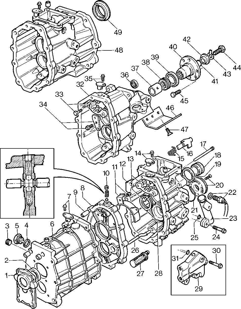
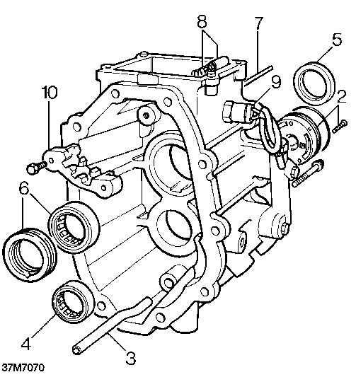
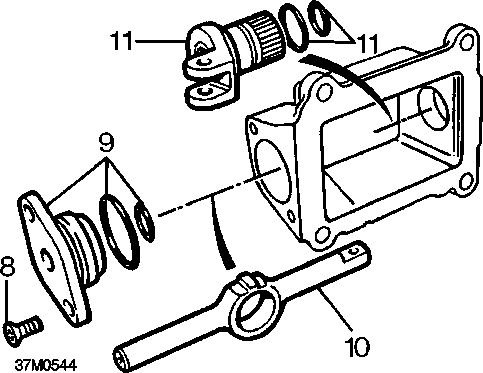
GEARBOX CASINGS
1. Front cover
2. Input shaft oil seal
3. Oil level plug
4. Washer
5. Oil drain plug
6. Gearcase
7. Spool retainer
8. Centre plate
9. Locating dowels
10. Selector plug - outer detent ball and spring
11. Splash shield
12. Extension housing - Types A and B gearbox
13. Gate plate
14. Spool retainer - Extension housing
15. Inhibitor cam spring
16. Inhibitor cam
17. Inhibitor cam shaft
18. Oil selector collar
19. Oil seal
20. Oil pump
21. ’O’ ring
22. Reverse light switch
23. Oil cooler by-pass
24. Bolt
25. ’O’ ring
26. Oil pick-up pipe
27. Oil filter
28. Oil pick-up ring
29. Oil cooler adaptor
30. Bolt
31. ’O’ ring
32. Extension housing - Type C gearbox
33. Gate plate - Type C gearbox
34. Inhibitor cam end plate - Type C gearbox
35. Spool retainer - Type C gearbox
36. Selector shaft oil seal - Type C gearbox
37. Spacer - Type C gearbox
38. Speedometer pinion - Type C gearbox
39. Oil seal - Type C gearbox
40. Output shaft drive flange - Type C gearbox
41. ’O’ring - Type C gearbox
42. Spacer - Type C gearbox
43. Tab washer - Type C gearbox
44. Drive flange bolt - Type C gearbox
45. Drive flange propeller shaft bolt - Type C gearbox
46. Support bracket - Type C gearbox
47. Support bracket bolt - Type C gearbox
48. Extension housing - Type D gearbox
49. Oil seal - Type D gearbox
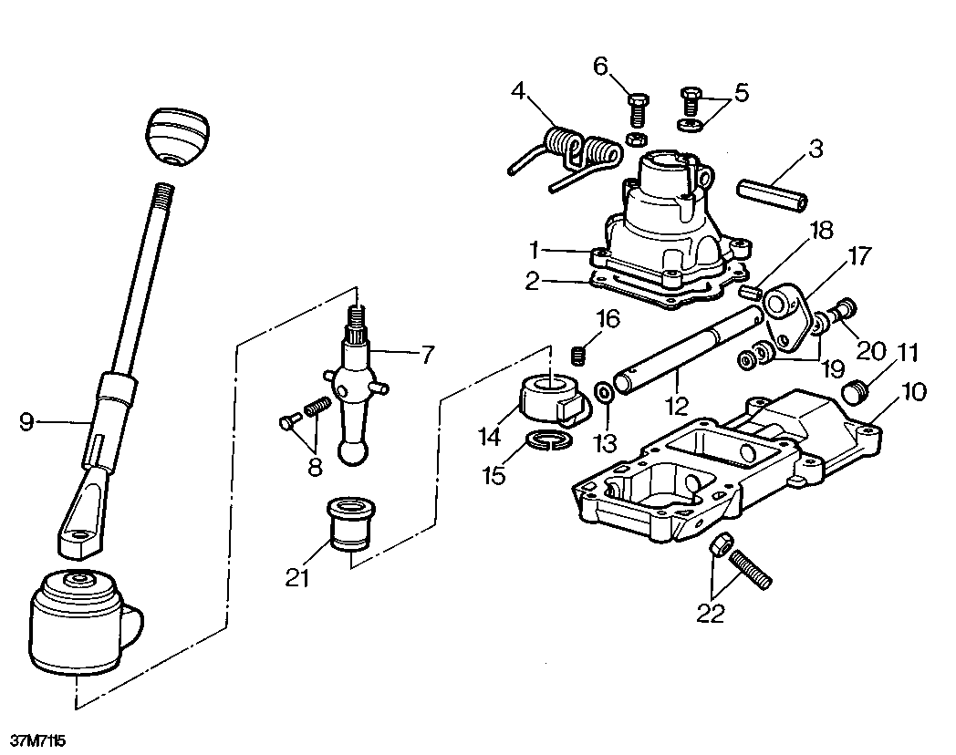

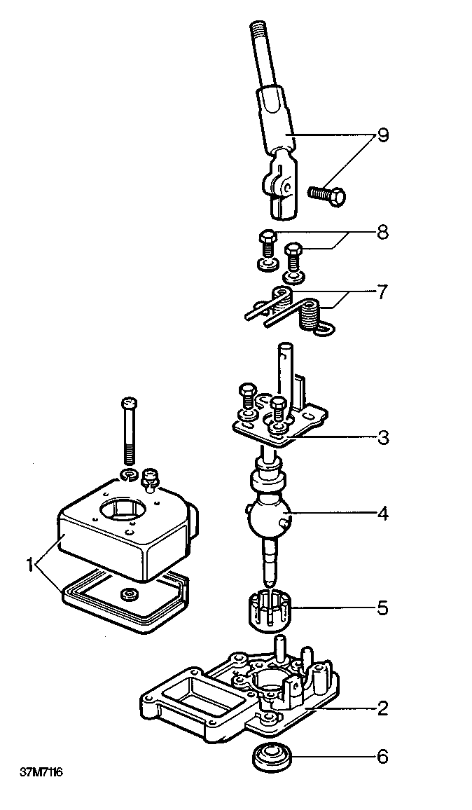
GEAR CHANGE HOUSING - TYPE A GEARBOX
1. Gear change housing
2. Gasket
3. Roll pin
4. Bias spring
5. Gear lever retaining bolt and washer
6. Gear change housing bolts
7. Gear lever
8. Nylon pad and spring
9. Gear lever extension
10. Remote housing
11. Blanking plug
12. Selector shaft
13. ’O’ ring
14. Trunnion
15. Circlip
16. Trunnion retaining screw
17. Selector quadrant
18. Roll pin
19. Shim
20. Pin
21. Ball pin seating
22. 5th gear stop screw and locknut

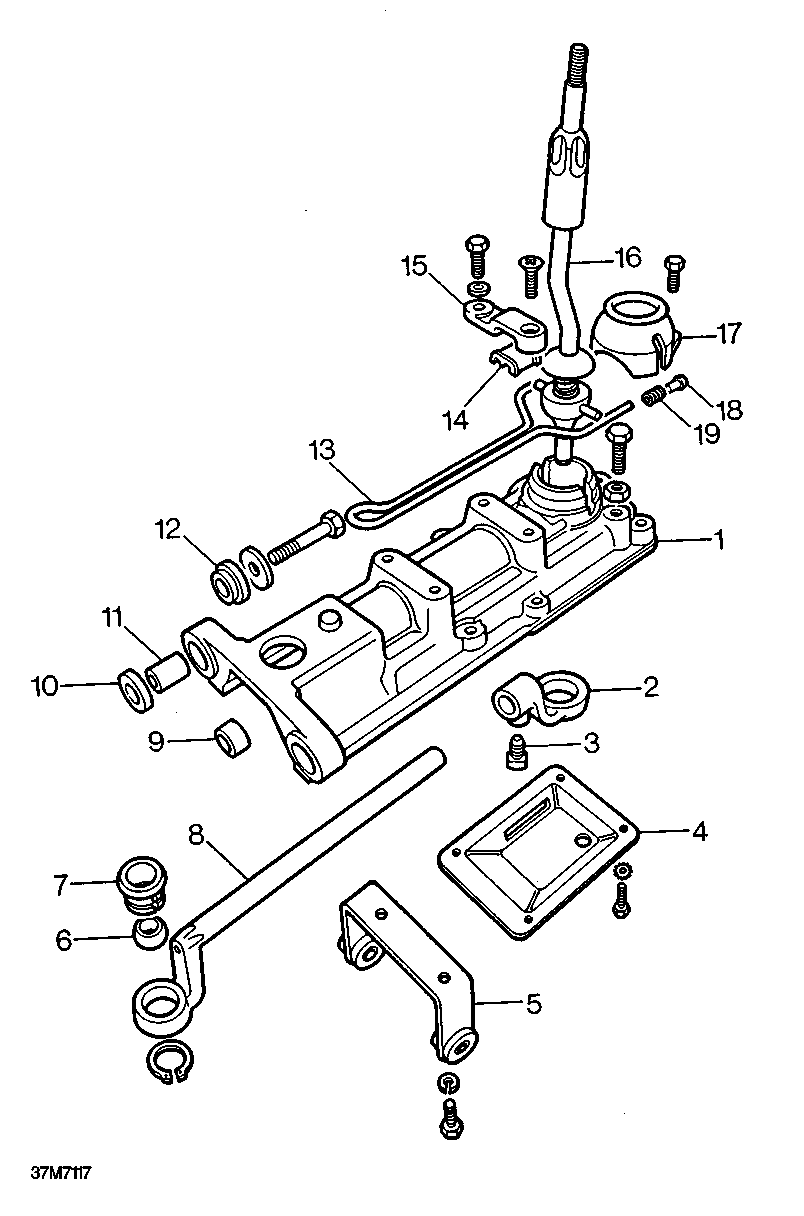
GEAR CHANGE HOUSING - TYPE B GEARBOX
|
1. |
Gearchange housing cover and gasket |
6. |
|
2. |
Gearchange housing |
7. |
|
3. |
Bias adjustment plate |
8. |
|
4. |
Lower gear lever |
9. |
|
5. |
Railko bush |
Lower gear lever housing oil seal Bias springs
Bias spring retaining bolts Upper gear lever and bolt

|
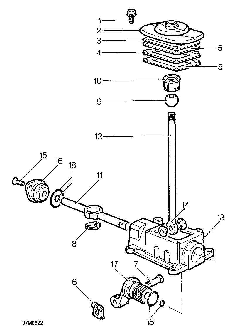
REMOTE GEAR CHANGE HOUSING - TYPE C GEARBOX |
||
|
1. Remote gear change housing |
10. |
Spacer |
|
2. Selector rod yoke |
11. |
Mounting rubbers |
|
3. Pinch bolt |
12. |
Flexible mounting |
|
4. Bottom cover plate |
13. |
Bias spring |
|
5. Remote gear change bracket |
14. |
Bridge plate liner |
|
6. Ball pin |
15. |
Bias spring bridge plate |
|
7. Ball pin seating |
16. |
Gear lever |
|
8. Selector rod |
17. |
Gear lever cap |
|
9. Selector rod bush |
18. 19. |
Plunger Anti-rattle spring |

|
TRANSFER BOX SELECTOR HOUSING - TYPE A GEARBOX |
||
|
1. Gaiter retaining bolt |
10. |
Nylon seat |
|
2. Gaiter |
11. |
Cross shaft |
|
3. Gaiter support plate |
12. |
Gear lever |
|
4. Gasket plate |
13. |
Selector housing |
|
5. Gaskets |
14. |
Bushes |
|
6. Spring clip |
15. |
Countersunk screws |
|
7. Clevis pin |
16. |
End cover |
|
8. Circlip retaining nylon seat |
17. |
Selector fork |
|
9. Gear lever ball |
18. |
’O’ rings |
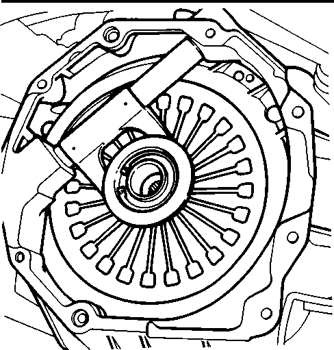
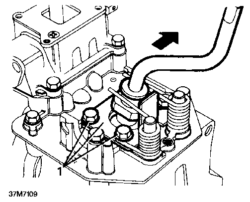
1. Iffitted: remove and discard clips retaining clutch release bearing pads, remove bearing and clutch release lever, recover pads.

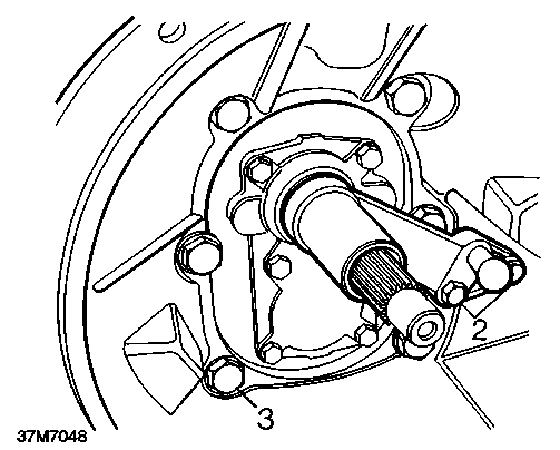
2. Remove 2 bolts securing release lever pivot post, remove post.
3. Remove 6 bolts securing clutch housing to gearbox, remove housing.

Clutch housing - Type B gearbox - Remove
Clutch housing - Type C gearbox - Remove
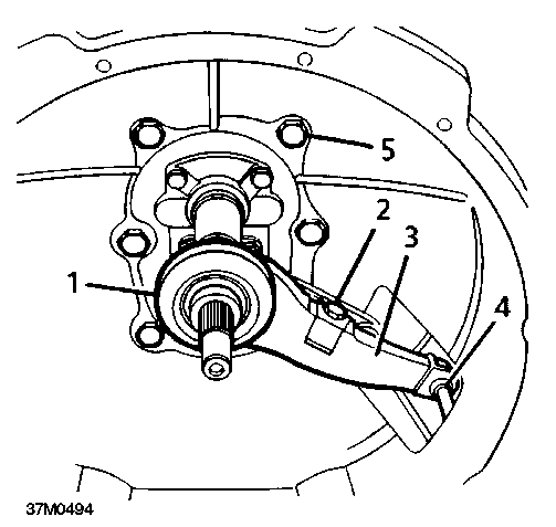
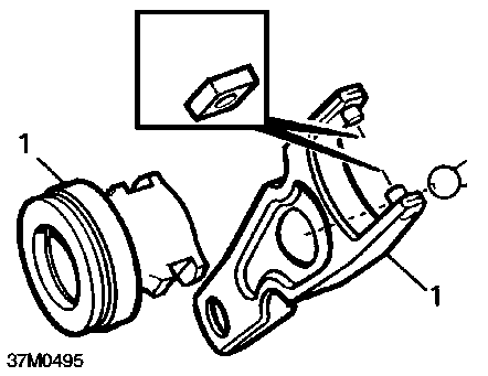
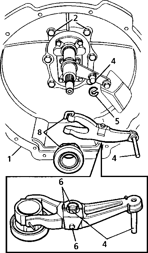
1. Pull clutch release lever off pivot post, remove lever and clutch release bearing.
1. Remove clutch release bearing.
2. Remove bolt securing spring clip to clutch release lever, remove clip.
3. Remove clutch release lever.
4. Remove ’C’ clip from release lever pivot post, discard clip.
5. Remove 6 bolts securing clutch housing to gearbox, remove housing.

NOTE: Dowel located.
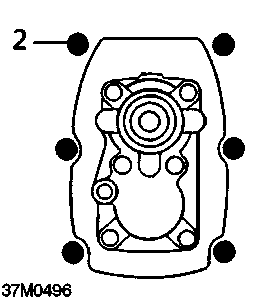
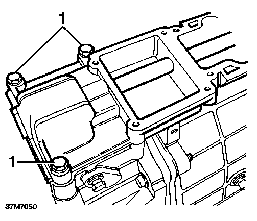
2. Remove 6 bolts securing clutch housing to gearbox, remove clutch housing.
^ NOTE: 2 longest bolts are fitted at dowel / \ locations and have plain washers under their heads.

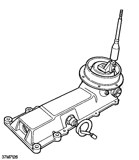
Gear change/selector housings - Type A gearbox - Remove
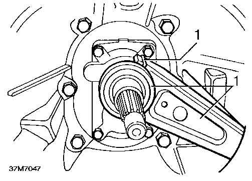
Clutch housing - Type D gearbox - Remove
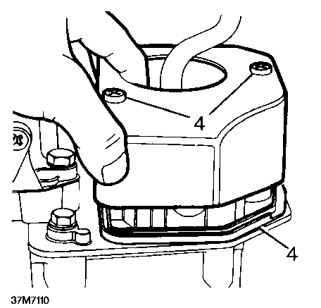
37M7119
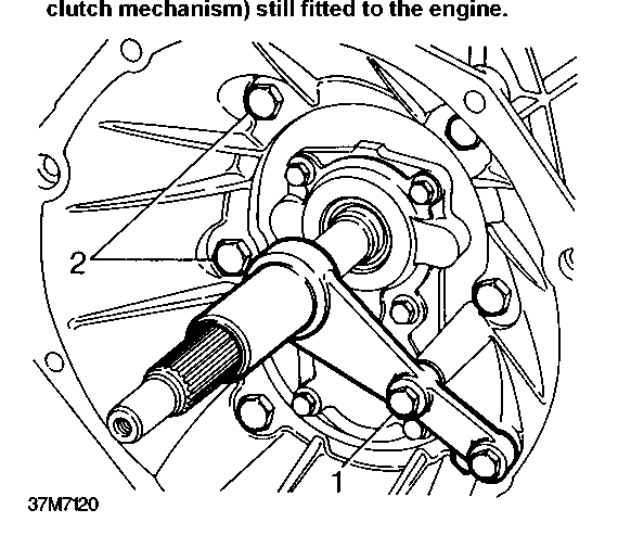

~ NOTE: Type D gearboxes have a standard / \ clutch housing adaptor which mates with both V8 and diesel engine clutch housings.The above illustration shows the gearbox removed at the clutch housing adaptor with the clutch housing adaptor (containing the
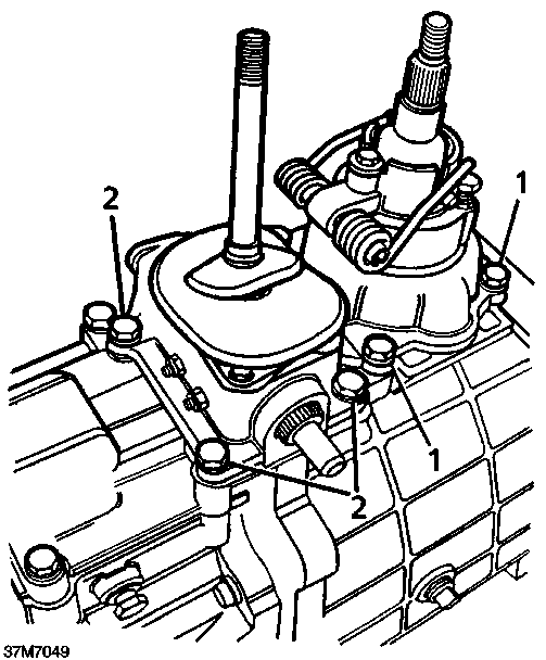
1. Remove 4 bolts securing gear change housing, remove housing.
NOTE: Dowel located.
Remove 4 bolts securing transfer box selector housing, remove housing.
1. Remove 2 bolts securing release lever pivot post. Remove post.
2. Remove 6 bolts securing adaptor housing to gearbox. Remove adaptor housing.
Remote housing - Type A gearbox - Remove
1. Noting their fitted position, remove 3 bolts securing remote housing, remove housing.
2. Remove 4 bolts securing transfer box selector housing, remove housing.
3. Noting their fitted position, remove 3 bolts securing gear change housing, remove housing.

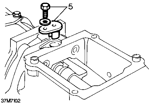
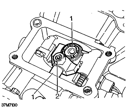
1. Remove 2 Torx screws securing gear change housing cover, remove cover; recover sealing rubber.
1. Remove and discard set screw securing selector quadrant.

2. Move selector shaft forwards, remove quadrant.
1. Noting fitted positions of mounting rubbers and washers, Rremove 2 bolts securing remote gearchange to extension housing, recover washers and mounting rubbers.
2. Remove 2 bolts securing remote gear change bracket to extension housing , recover washers and mounting rubbers.
3. Release remote gear change from extension housing, disconnect selector rod from selector shaft pin.
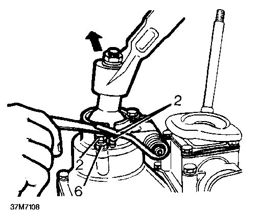
1. Remove and discard set screw securing yoke.
2. Move selector shaft forwards, remove yoke.
Remote gear change - Type D gearbox - Remove

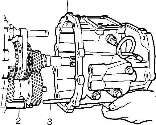
1. Remove 4 bolts securing remote gear change to extension housing.
2. Release remote gear change from extension housing.
Gear change lever yoke - Type D gearbox -Remove
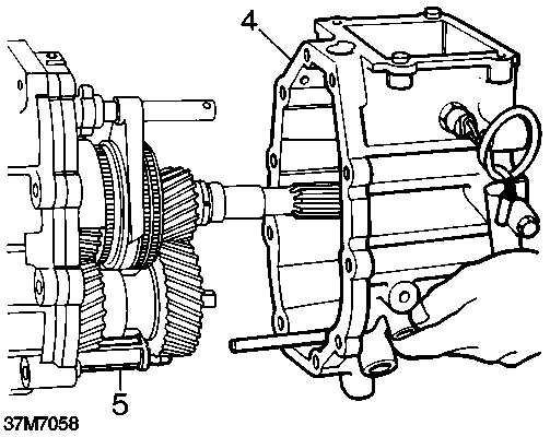
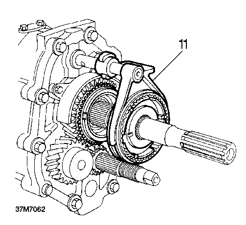
Extension housing - Types A and B gearbox -Remove
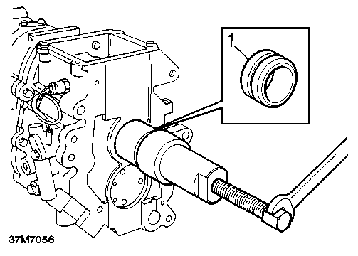
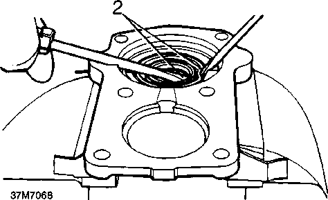
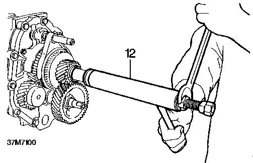
1. Thread a 12mm bolt into the end of the output shaft and using tool LRT-37-009 and LRT-37-010 withdraw oil seal collar.
2. Remove reverse/5th gear selector spool retainer.
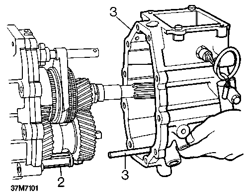
3. Remove 10 bolts securing extension casing noting position of longer bolts.
1. Remove and discard set screw securing yoke.
2. Move selector shaft forwards. Remove yoke.

Extension housing - Type C gearbox - Remove
4. Place a suitable container underneath the box to catch any oil spillage and remove the extension housing.
5. Remove oil filter.
6. Secure centre plate to gear casing with 2 bolts 8 x 35mm.
1. Remove and discard self-locking nut securing selector shaft pin to selector shaft; remove pin.
2. Carefully prise speedometer pinion housing and gear out of extension housing, remove and discard 'O' ring.
3. Remove 5th gear spool retainer, remove and discard 'O' ring.
4. Noting their fitted position, remove 10 bolts securing extension housing to gearcase.
5. Using a soft faced mallet, tap extension housing to free it from locating dowels.
6. Remove extension housing.
^ NOTE: Speedometer drive gear may be a / \ tight fit on output shaft and this can prevent removal of extension housing. Insert suitable blocks of wood between extension housing and centre plate and carefully lever extension housing away until drive gear is released.
7. Remove and discard selector shaft oil seal.
8. Secure centre plate to gearcase with 2 bolts 8 x 35mm.
Extension housing - Type D gearbox - Remove
1. Remove reverse gear/5th gear selector spool retainer.
2. Remove 10 bolts securing extension case to main gearcase, noting position of longer bolts.
3. Place a suitable container underneath the box to catch any oil spillage.
4. Using a soft faced mallet, tap extension housing free from its location dowels.
5. Remove extension housing.
6. Remove oil filter.
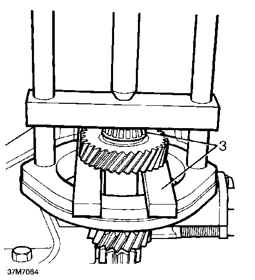
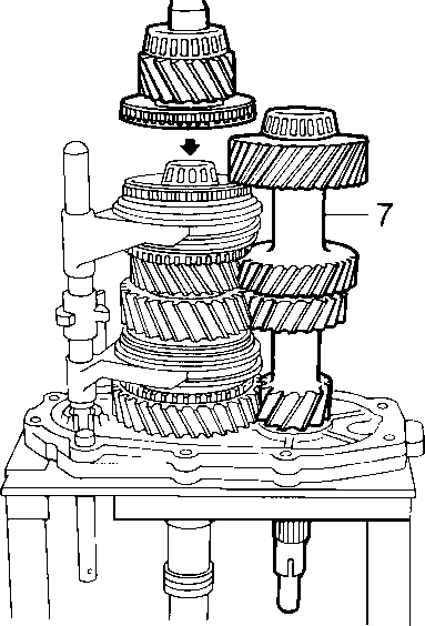
5th and Reverse gear - Remove
37M7061A

1. Using a suitable two legged puller remove 5th gear layshaft support bearing track from the end of layshaft.
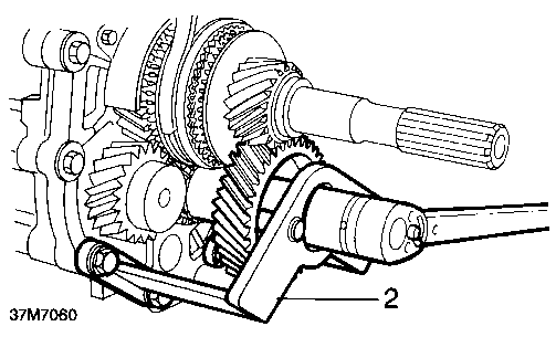
2. Using tool LRT-37-023 to hold the 5th laygear, remove the 5th laygear nut.
3. Remove thrust collar segments, retaining ring and segments, drift out the roll pin.
4. Latergearboxes: Remove split washer securing 5th laygear to shaft.
5. Remove 5th laygear.
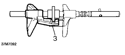
6. Remove mainshaft rear support bearing track using tools LRT-37-009 and LRT-37-024.
7. Remove 12mm bolt from end of mainshaft.
8. Remove mainshaft 5th gear with synchromesh baulk ring.
9. Remove mainshaft 5th gear split needle roller bearing.
10. Remove circlip securing 5th gear synchromesh hub.
11. Rotate selector spool clear of synchro hub fork and remove 5th and reverse synchromesh hub assembly complete with fork and spool.
12. Remove mainshaft reverse gear complete with needle roller bearing and bush noting selectable spacer between reverse gear bush and centre plate bearing.
13. Remove layshaft reverse gear.
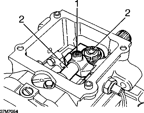
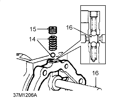
14. Remove centre plate detent plug, spring and ball.
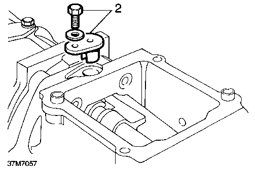
15. Remove 2 bolts securing spool retainer, remove retainer.
16. Remove’slave’bolts.
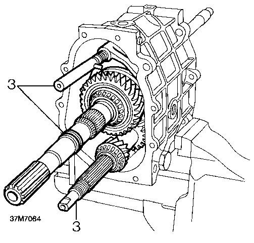
Mainshaft and layshaft - Remove Mainshaft - Dismantle
1. Align selector shaft pin with slot in centre plate and using wooden blocks and hide mallet, drive off centre plate.
2. Collect detent ball and spring, remove bearing tracks and shims.
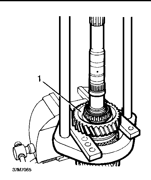
1. Using LRT-99-002 and support bars under 1st gear, press mainshaft support bearing from mainshaft.
3. Remove layshaft, mainshaft and selector shaft from casing as complete unit.
4. Remove input shaft, and 4th gear baulk ring. (If not already removed with mainshaft).

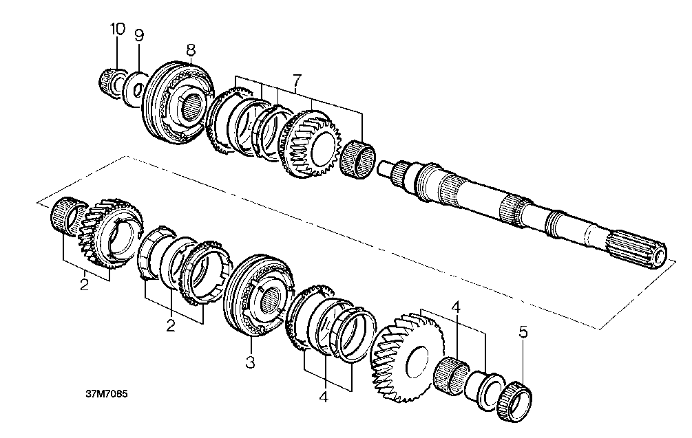
37M7067
5. Remove spacer, 3rd/4th gear synchromesh selector hub, synchromesh baulk rings, 3rd gear and needle bearing.
2. Remove 1st gear, bush needle bearing and synchromesh baulk rings.
3. Remove 1st/2nd gear synchromesh selector hub, 2nd gear synchromesh baulk rings, second gear and needle bearing.
4. Invert mainshaft and using LRT-99-002 and support bars under 3rd gear, press off pilot bearing
Centre plate - Dismantle
Gearbox casing
Degrease and clean all components. Inspect casing for damage, cracks and stripped threads.
1. Fit level plug.
2. Fit new copper washer to drain plug.
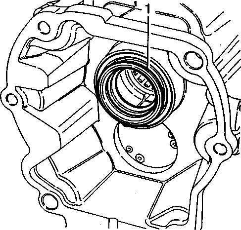
Front Cover - Dismantle
1. Remove front cover and remove bearing tracks. Check that spring clips are intact.
2. Remove oil seal from cover. DO NOT fit new seal at this stage.
37M7069A
1. Remove bearing tracks and shims and check for wear and damage.
2. Inspect for damage and selector rail bore for wear.
3. Remove splash shield if required.
4. Press out reverse idler gear shaft using suitable press and check for wear.
5. Remove idler gear, needle bearing and spacer and check for wear and damage.
6. Check centre plate detent balls for wear and springs for distortion, replace as necessary.
7. Check that threads of detent plug are not damaged.
~ NOTE: Patchlok plug may be re-used / \ provided threads are undamaged.

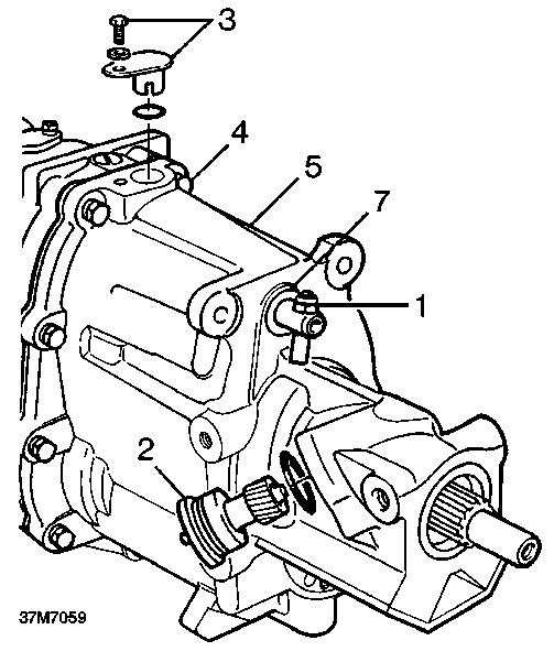
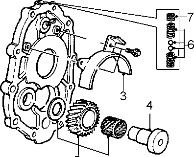
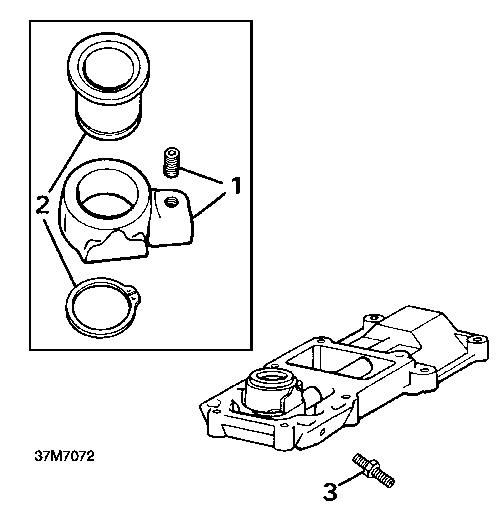
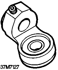
Extension housing - Types A and B gearbox -Overhaul
1. Examine for damage to threads and machined faces.
~ NOTE: Types A and B gearbox extension / \ housing shown.
2. Remove three screws and remove oil pump.
3. Remove oil pick-up pipe and check for obstruction.
4. Drift out layshaft support bearing.
5. Remove mainshaft rear oil seal.
6. Drift out mainshaft support bearing and oil pick up ring.
7. Remove shaft retaining reverse inhibition cam.
8. Remove reverse inhibition cam and spring.
9. Remove reverse light switch and sealing washer.
10. Remove gate plate.
11. Check all components for wear and renew as required.
Type C gearbox -As forA and B Types and including the following:
12. Recover speedometer dive gear and spacer.
13. Check speedometer drive gear for wear and damage, renew if necessary.
14. Check speedometer pinion for wear and damage. Check that scrolling on shaft is clear; renew pinion and shaft if necessary.
15. Check slots in 5th gear spool guide for wear, renew spool guide if necessary.
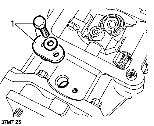
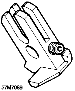
Type C and D gearboxes
^ CAUTION: The rear mainshaft oil seal /{\ fitted to Type C and D extension housings is different to Types A and B. When levering out seal, take care not to damage the seal location surfaces.
37M7124
^ NOTE: Type D gearbox extension housing / \ shown.
1. Lever out mainshaft oil seal, taking care not to damage the location surfaces.
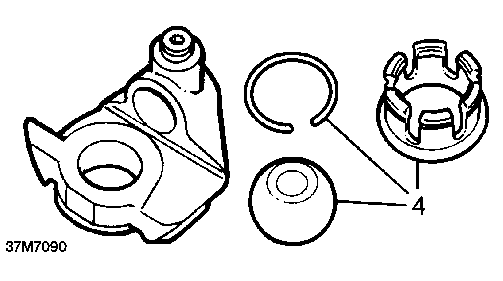
Reassembly
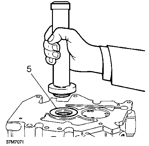
1. Smear a light coat of petroleum jelly into the pump recess.
2. Renew ’O’ ring and press pump unit firmly into recess.
^ NOTE: Ensure ’TOP’ marking on pump is / \ to top of casing.
3. Tap pump lightly at edges until fully home.
^ NOTE: Ensure good thread engagement / \ before tightening.
Gear change/selector housings - Overhaul
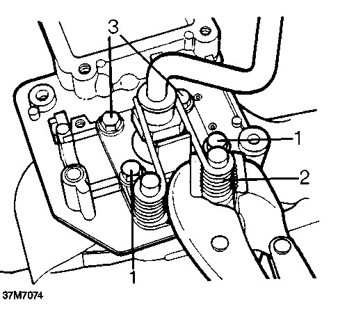
Gear change housing - Type A gearbox Dismantle
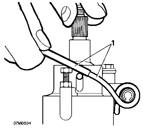
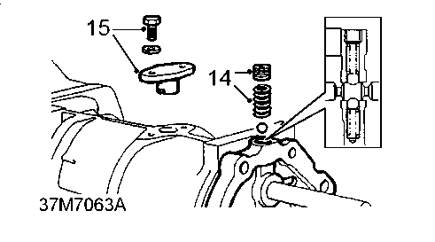
1. Using a suitable piece of tubing, release both ends of bias spring from ball pins.
2. Slacken locknuts and remove bias spring adjusting screws.
3. Drift out roll pin, remove bias spring.
4. Fit new mainshaft support bearing.
5. Fit new mainshaft rear oil seal using tool LRT-37-014.
6. Fit new Layshaft support bearing.
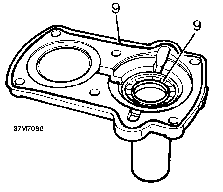
7. Fit new oil pick-up ring (Align tag with centre of drain slot).
8. Examine gate plate and renew if worn or damaged.
9. Refit reverse light switch with new copper washer. Tighten to 24 Nm.
10. Refit reverse inhibition cam and spring.
11. Apply Hylogrip 640 and refit shaft.
12. Refit oil pipe, bend uppermost.


4. Remove extension from lower gear lever.
5. Remove bolt and special washer securing lower gear lever.
6. Carefully withdraw lower gear lever from housing ensuring that spring loaded nylon pad is retained during removal.
A WARNING: Personal injury may result if pad is not retained.
7. Release nylon pad, recover spring.
8. Clean all components.
Inspection
1. Check lower gear lever ball pin for wear, replace if necessary.
CAUTION: If lower gear lever is to be replaced then ball pin seating, located in remote housing should also be replaced.
2. Check nylon pad and spring for wear and damage, replace if necessary.
3. Check bias spring roll pin for damage, replace if necessary.
Reassemble
1. Smear ball pin with multi - purpose grease and fit spring and nylon pad.
2. Depress nylon pad against spring pressure, position lower gear lever in housing.
CAUTION: Ensure nylon pad is facing
j\ away from bias spring location.
3. Fit lower gear lever retaining bolt and special washer, tighten bolt to 15 Nm.
4. Fit extension to lower gear lever.
5. Position roll pin to housing, fit roll pin.
6. Fit bias spring adjusting screws and locknuts.
7. Using a suitable piece of tubing locate both ends of bias spring over ball pins.
~ NOTE: Do not adjust bias spring at this / \ stage.

Remote housing - Type A gearbox Dismantle
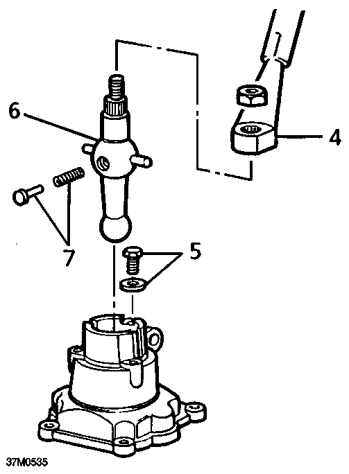
1. Remove setscrew securing trunnion to selector shaft, remove trunnion.
2. Remove and discard circlip securing ball pin seating to trunnion, remove seating.
3. Slacken locknut, remove 5th gear stop screw.
CAUTION: Retain shim(s).
4. Remove blanking plug from end of remote housing.
5. Remove setscrew securing quadrant to selector shaft, remove quadrant.
6. Remove selector shaft from remote housing, remove and discard ’O’ ring.
7. Remove and discard circlip retaining rollers and pin to quadrant.
8. Remove pin, recover rollers.
Inspection
1. Check selector shaft and bore in remote housing for wear.
2. Check quadrant rollers and pin for wear.
3. Check ball pin seating for wear.
4. Replace worn components as necessary.

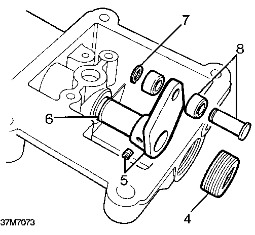
Reassemble
Gear change housing - Type B gearbox

Dismantle
1. Lubricate selector shaft and new ’O’ ring with gearbox oil.
2. Fit ’O’ ring to selector shaft.
3. Fit shaft to remote housing.
4. Position rollers to quadrant, fit pin and secure with new circlip.
CAUTION: Ensure that head of pin is on opposite side of quadrant to selector shaft boss.
5. Fit quadrant to selector shaft.
6. Apply Loctite 270 to threads of setscrew, fit and tighten setscrew.
7. Apply Loctite 270 to threads of blanking plug, fit and tighten plug.
8. Smear ball pin seating with multi - purpose grease.
9. Position ball pin seating in trunnion, secure with a new circlip.
10. Position trunnion on selector shaft.
11. Apply Loctite 270 to threads of setscrew, fit and tighten setscrew.
12. Fit 5th gear stop screw, fit but do not tighten locknut.
1. Remove bolts retaining bias springs.
A WARNING: To avoid personal injury,
restrain each spring in turn with a pair of grips while the bolts are being removed.
2. Remove the two springs.
~ NOTE: 5th gear stop screw adjustment is / \ carried out during gearbox reassembly.
3. Remove remaining bolts to release lower lever assembly.
4. Remove and discard Railko bush.
5. Remove and discard oil seal.
Inspection
1. Check ball cross pin slots in gear change housing for wear.
2. Check ball and pins for wear.
3. Check bias springs for distortion.
4. Replace worn components as necessary.
Reassemble
1. Apply multi-purpose grease to ball and cross pins.
2. Apply multi-purpose grease to new Railko bush and fit to gear change housing.
^ CAUTION: Ensure that the slots in each /{\ bush are aligned with slots in housing.
3. Lubricate a new oil seal with gearbox oil.
4. Fit oil seal using a suitable mandrel.
5. Position gear lever to gear change housing ensuring ball cross pins are located in slots in housing and Railko bush.
6. Position bias spring adjustment plate to gear change housing,
7. Apply Loctite 270 to threads of 2 short bias adjustment plate bolts.
8. Fit bolts to secure front of bias adjustment plate and tighten to 25 Nm.
9. Position bias spring to pillar ensuring longest end of spring is against gear lever.
10. Apply Loctite 270 to threads of 2 long bias bias adjustment plate bolts.
11. Restrain bias spring using a suitable pair of grips,ensure short end of bias spring is positioned on outside edge of bolt hole.
Remote gear change - Type C gearbox Dismantle
A WARNING: Personal injury may result if bias spring is not retained.
12. Fit bolt and washer ensuring end of bias spring is retained beneath washer; tighten bolt to 25 Nm.
13. Repeat procedure for remaining bias spring.
1. Remove 2 bolts and 2 countersunk screws securing bias spring bridge plates.
2. Remove bridge plates, bridge plate liners and bias spring.
3. Remove 4 bolts and washers securing bottom cover plate, remove plate.
4. Remove bolt securing gear lever cap, remove cap.
5. Remove gear lever, recover anti-rattle spring and plunger.
6. Remove pinch bolt securing selector rod yoke, remove yoke.
7. Withdraw selector rod from remote housing.
8. Clean components.

Inspection
Remote gear change - Type D gearbox
~ NOTE: The remote gear change fitted to / \ Type D gearboxes is not repairable item. It must be renewed if it is found to be excessively worn.
1. Check selector rod bushes in remote housing for wear.
^ NOTE: Bushes may be pressed in and out / \ of remote housing using a hand press and suitable mandrel.
2. Check selector rod for wear, replace if necessary.
3. Check anti - rattle spring for distortion and plunger for wear; replace if necessary.
4. Check gear lever ball pin, cross pins and bush selector rod yoke balls for wear, and replace if necessary. If yoke balls are worn, remove and discard circlip, press ball and seating out of yoke.
5. Lubricate replacement ball and seating with multi - purpose grease and press into yoke; secure using new circlip.
6. Check bias spring for distortion, replace if necessary.
7. Check condition of mounting rubbers, replace as a set if necessary.
Reassemble
1. Lubricate selector rod and bushes with multi -purpose grease, insert rod in remote housing.
2. Lubricate gear lever ball pin and selector rod yoke balls with multi - purpose grease.
3. Fit yoke to selector rod, fit and tighten pinch bolt.
4. Assemble anti - rattle spring and plunger to gear lever.
5. Fit gear lever ensuring ball pin is located in yoke and anti - rattle spring and plunger are not displaced.
6. Fit gear lever cap, fit and tighten bolt.
^ NOTE: Do not fit bottom cover plate at this / \ stage.
7. Slacken bias spring adjustment bolt locknuts.
8. Fit bias spring, bridge plate liners and bridge plates.
9. Fit and tighten bolts and countersunk screws.
^ NOTE: Final adjustment of bias spring is / \ carried out after remote gear change is fitted to gearbox.
Transfer box selector housing - Type A gearbox -Overhaul
Dismantle
1. Slide gaiter off gear lever.
2. Remove 4 bolts securing gaiter support plate and gate plate.
3. Remove gaiter support plate and gate plate, discard gaskets.
4. Remove and discard spring clip retaining selector fork clevis pin.
5. Remove clevis pin from selector fork, remove and discard 2 bushes.
6. Remove and discard circlip retaining nylon ball seating.
7. Remove gear lever, recover nylon seating and ball
8. Remove 2 countersunk head screws securing end cover to housing.
9. Remove end cover, remove and discard 2 ’O’ rings.
10. Withdraw cross shaft.
11. Remove selector fork, remove and discard 2 ’O’ rings.
12. Clean all components.

Inspection
1. Check gaiter for splits and damage.
2. Check nylon seating and ball for wear, replace if necessary.
^ CAUTION: Seating and ball should be /{\ renewed as an assembly.
3. Check selector fork and clevis pin for wear.
4. Check cross shaft and end cover for wear.
5. Replace components as necessary.
Reassemble
1. Smear new ’O’ rings with gearbox oil and fit to selector fork, position fork in housing.
2. Smear cross shaft with multi - purpose grease and locate longest end of shaft in selector fork.
3. Smear new ’O’ rings with gearbox oil and fit to end cover.
4. Position end cover on cross shaft, fit and tighten countersunk screws.
5. Assemble ball and nylon seating to gear lever ensuring that groove in seating is towards cross shaft.
6. Smear ball and nylon seating with multi -purpose grease and locate in cross shaft; retain with a new circlip.
7. Position new bushes to gear lever, locate in selector fork and fit clevis pin.
8. Fit new spring clip to retain clevis pin.
9. Position gate plate and gaiter support plate to housing, use new gaskets.
10. Fit retaining bolts and tighten to 15 Nm.
11. Fit gaiter.
Synchromesh assemblies - Overhaul
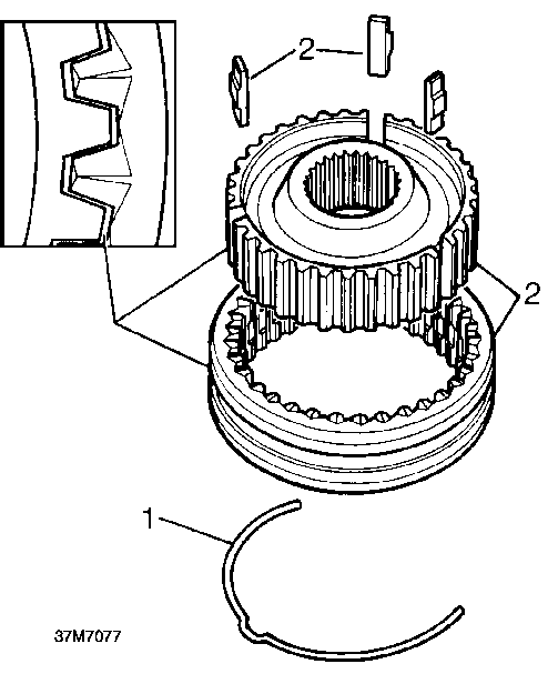
1. Remove spring clips from both sides of assembly.
2. Remove slippers and separate the hub from the sleeve.
3. Examine all parts for damage and wear including spring clips for tension.
4. Check no excessive radial movement exist between inner members and mainshaft splines.
5. Examine inner and outer splines for wear.
|
Assy |
Hub |
Sleeve |
Against Gear |
|
1st/2nd |
- |
1 Notch |
1st |
|
2 gear side |
- |
2nd |
|
|
3rd/4th |
- |
3 Notches |
3rd |
|
- |
- |
4th |
|
|
5th/Rev |
- |
5 Notches |
5th |
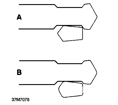
6. Examine the dog teeth on all gears for wear and damage.
^ NOTE: Example ’A’ shows a tooth in good / \ condition. Example ’B’ shows the rounded corners of a worn tooth.
7. Replace unit if excessively worn.
Reassembly
8. Refit inner hub to sleeve.
^ NOTE: Hubs and sleeves have a master / \ spline combination and can only be assembled one way. The sleeves are further identified with a series of half moon notches which clearly identify which side of the assembly faces which gear. Ensure the slot in the hub aligns with the centre notch on the sleeve.
9. Fit slippers and secure with a spring each side of the synchromesh assembly ensuring the step on each spring locates on a different slipper.
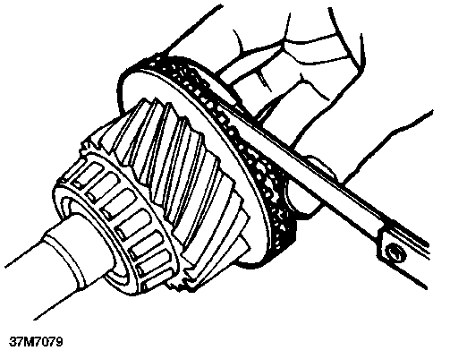
Checking baulk ring clearances
Check clearance of all baulk rings and gears by pressing the baulk rings against the gear and measuring the gap. The minimum clearance should be 0.5mm (0.020in).
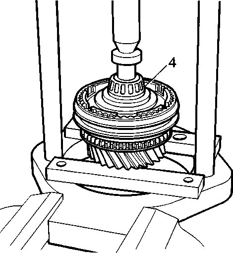
Input shaft - Overhaul
1. Examine the gear and dog teeth for wear and
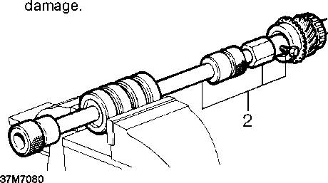
2. Using tool LRT-99-004 and LRT-37-004
remove pilot bearing track.
^ NOTE: Ensure that the bearing is / \ supported by the lip inside LRT-37-001.
^ NOTE: 5th and reverse synchromesh hubs / \ have different springs noted by their yellow colour.
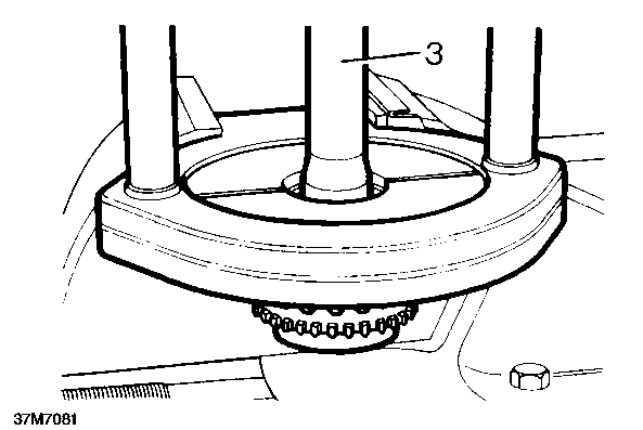
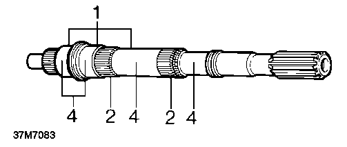
Mainshaft - Inspection

3. Using LRT-37-001 and LRT-99-002 remove taper roller bearing.
4. Support the shaft under LRT-99-002 and press in a new pilot bearing track.
1. Examine bearing journals for wear and scores.
2. Examine splines for wear and damage.
3. Use an air line to check that the main oil feed from pump and feed to spigot bearing are clear.
4. Check oil feed holes to roller bearing are clear.
5. Using LRT-99-002, Collets LRT-37-001 and adapter LRT-37-002 fit a new taper bearing.
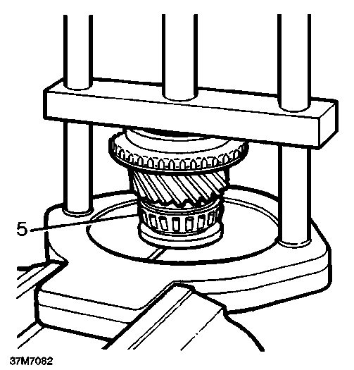
Layshaft - Overhaul
1. Using extractor tool LRT-99-002 and collets LRT-37-022 withdraw layshaft bearings.
2. Examine layshaft for wear and damage.
^ NOTE: Layshaft and layshaft 5th gear / \ fitted to later gearboxes are machined to enable fitment of a split washer to prevent gear movement on shaft. The modified layshaft, gear and split washer may be fitted to early gearboxes as an assembly.
3. Using press LRT-99-002, and support bars fit new taper roller bearings.

Mainshaft - Reassembly
1. Clamp mainshaft in protected vice jaws, output end upwards.
2. Fit 2nd gear needle roller bearing, 2nd gear and synchromesh baulk rings onto mainshaft. (Rotate each baulk ring to ensure they locate onto each other).
3. Assemble the 1st and 2nd synchromesh selector hub onto mainshaft spline, (note 2nd speed side marking). Ensure that baulk ring has located correctly inside hub. (Rotate the ring slightly as the hub is lowered).
4. Fit 1st gear synchromesh baulk rings, needle roller bearing, 1st gear and bush onto mainshaft ensuring baulk rings locate correctly inside selector hub.
5. Using LRT-99-002, bearing guide LRT-37-019, collets LRT-37-001 and adaptor LRT-37-002
press on mainshaft taper roller bearing taking care not to disturb the lay of the synchromesh baulk rings and gears.
6. Check the end float of the 1st and 2nd gear assembly using a feeler gauge between the gear and mainshaft bearing.
Maximum clearance:
1st gear: 0.05 - 0.20mm (0.002 - 0.008 in) 2nd gear: 0.04 - 0.21mm (0.0016 - 0.0083 in)
7. Invert mainshaft in vice and fit 3rd gear needle roller bearing, third gear and synchromesh baulk rings.
8. Assemble 3rd/4th gear synchromesh selector hub (note 3rd speed side markings) onto mainshaft splines taking care to locate the baulk rings into recesses in the selector hub.
9. Fit spacer.

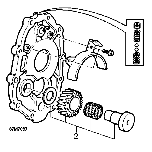
Reverse idle gear - Reassembly
1. Examine components for wear and damage.
10. Using LRT-99-002 press on new pilot bearing. Check end float of 3rd gear assembly as in step 6.
Maximum clearance:
0.11 - 0.21mm .
2. Assemble reverse idle gear needle roller bearing, idle gear, spacer and shaft and using suitable tool, press into centre plate. Maximum clearance:
0.04 - 0.38mm (0.0016in - 0.015in)

Selectors - Inspection
1. Examine selector rail and pins for wear and damage.
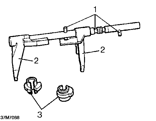
2. Examine selector forks for wear and damage.
^ NOTE: The selector rail and fork is only / \ supplied as a complete assembly.
3. Examine interlock spools for wear and damage.
Selector quadrant - Type A gearbox Examine selector quadrant and check for wear.
Selector yoke - Type C gearbox
4. Remove snap ring and examine selector yoke assembly.
Selector yoke - Type B and D gearboxes
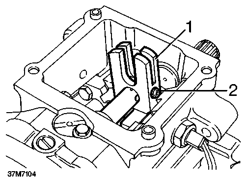
Assembling selectors. GEARBOX REASSEMBLE
1. Rest 1st/2nd fork and shaft assembly on bench and locate pin in jaw of fork.
2. Fit interlock spool and 3rd/4th fork and engage spool in jaw of fork.
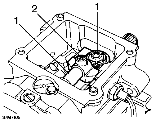
3. Slide spool and fork towards 1st/2nd selector until slot in spool locates over pin keeping the spool engaged in 3rd/4th fork jaw.
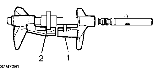
Mainshaft and layshaft end float
^ NOTE: The end float setting for both the / \ mainshaft and the layshaft has to be determined before the gear box can be reassembled. This is achieved by clamping the mainshaft and layshaft separately between the centre plate and main casing and measuring the movement on each shaft with a Dial test indicator.
The end float setting for the mainshaft and layshaft is 0.01 - 0.06mm (0.0004 - 0. 0024in).
Shims to make up the required clearances are placed under the bearing tracks of the centre plate.
Shimming
1. Fit bearing tracks to main casing front cover.
2. Fit front cover to casing without oil seal.
3. Clamp casing in vice with front cover downwards.
4. Fit input shaft. Do not fit 4th gear baulk ring.
5. Fit mainshaft assembly to input shaft.
6. Fit mainshaft bearing shim and track to centre plate.

7. Fit centre plate and bolt down using 8 ’slave’ bolts.
8. Fit large ball bearing to rear of mainshaft.
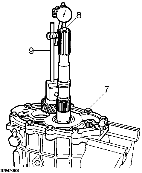
9. Mount dial test indicator.
10. Rotate mainshaft to settle bearings.
11. Lift mainshaft and note reading.
12. Dismantle and substitute shims if reading incorrect.
13. Repeat procedure.
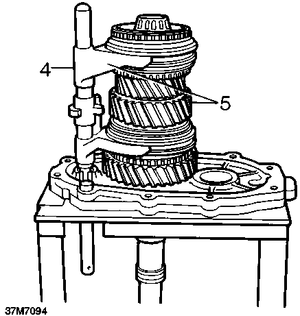
14. Remove mainshaft assembly and repeat procedure for layshaft.
15. Dismantle assembly in preparation for assembly on stand.
Assembling mainshaft and layshaft to centre plate
1. Secure centre plate to workstand.
2. Fit selected shims and bearing tracks.
3. Fit inboard detent ball and spring, use a dummy bar to temporarily hold the ball in place.
4. Check both synchromesh units are in neutral and fit selector shaft assembly to mainshaft.
5. Fit mainshaft and selectors as complete unit to centre plate aligning pin with slot in plate.
6. Fit 4th gear synchromesh baulk ring.
8
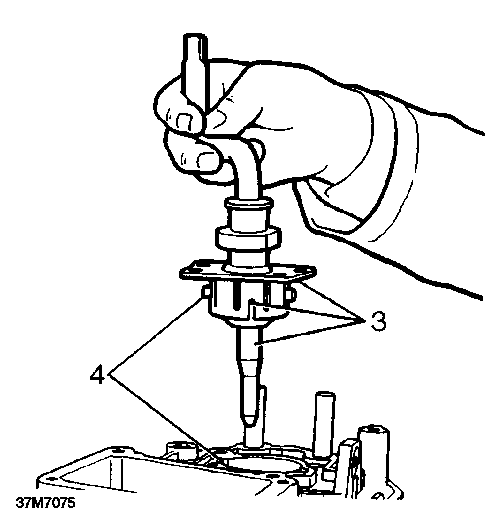
37M7095
7. Fit layshaft whilst lifting mainshaft to clear layshaft rear bearing.
8. Lubricate pilot bearing and fit input shaft.
9. Fit oil seal to front cover. Ensure seal is fitted down to shoulder. Apply Hylosil RTV 102 to front cover as shown.
^ NOTE: Early type seal - unwaxed -/ \ lubricate seal with gearbox oil.
Later type seal - wax coated - fit seal dry.
10. Fit bearing tracks and clips to main case and fit front cover. Seal fixings with Hylogrip 640.
11. Apply Hylosil RTV 102 and fit main casing to centre plate.
12. Bolt casing and centre plate together using 2 or 3 ’slave’ bolts.
13. Fit new ’O’ ring and fit spool retainer.
14. Remove casing from stand and clamp in vice.

Reverse and 5th gear - Reassembly
1. Fit mainshaft reverse gear selectable washer, bush and needle bearing.
2. Fit mainshaft reverse gear and synchromesh baulk ring.
3. Fit layshaft reverse gear.
4. Assemble selector spool, selector fork and reverse /5th gear synchromesh hub. Fit as one assembly to mainshaft splines and selector shaft. (Ensure synchromesh baulk ring locates inside hub).
5. Fit new circlip.
^ NOTE: The fit of the circlip is controlled by / \ the selectable washer behind the reverse gear. Adjust to 0.005 - 0.055mm (0.0002 -
0.0021in).
6. Fit 5th gear split needle bearing.
7. Fit 5th gear and 5th gear synchromesh baulk ring to mainshaft, fit layshaft 5th gear.
8. Latergearboxes: Fit split washer to retain layshaft 5th gear.
~ NOTE: Bevelled side of washer must face / \ towards gear.
9. Fit new mainshaft thrust collar roll pin. Locate 5th gear thrust segments and retaining ring.
37M7099
10. Using LRT-37-023 to hold layshaft 5th gear, tighten the layshaft 5th gear nut to 220 Nm.
11. Stake layshaft 5th gear nut.

12. Using tool LRT-37-015 and LRT-37-021 press mainshaft rear support bearing track to collar on mainshaft.
13. Apply small amount of heat and fit layshaft rear support bearing.
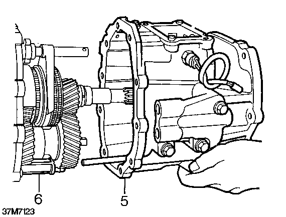
Extension housing - Type A and B Gearbox -Refit
1. Remove all ’slave’ bolts from centre plate and casing.
2. Refit oil filter.
3. Apply Hylosil RTV 102 to mating surfaces and fit extension housing ensuring oil pipe locates in filter and roller bearings are not dislodged.
CAUTION: Do not use force, if necessary, remove extension housing and re - align oil pump drive.
4. Bolt extension housing to centre plate and main casing.
14. Fit centre plate detent ball and spring.
15. Fit and tighten plug to 25 Nm.
^ NOTE: Patchlok plug may be re-used / \ provided threads are undamaged.
16. Move selector shaft and check that detent balls can be felt to engage in detent.

5. Apply Hylosil RTV 102 to extension case spool retainer, fit retainer and tighten bolt to 8 Nm.
Extension housing - Type C gearbox - Refit
1. Lubricate a new selector shaft oil seal with gearbox oil.
2. Fit selector shaft oil seal.
3. Refit oil filter.
4. Apply Hylosil RTV 102 to mating surfaces.
5. Fit extension housing ensuring oil pick - up pipe locates in filter and drive locates in oil pump.
^ CAUTION: Do not use force, if necessary,
/j\ remove extension housing and re - align oil pump drive.
6. Fit extension housing bolts and tighten by diagonal selection to 25 Nm.
7. Fit spacer
8. Position speedometer drive gear on output shaft splines.
9. Using a round nosed punch, carefully tap speedometer drive gear into position.
10. Smear a new ’O’ ring with gearbox oil and fit to speedometer pinion housing.
11. Lubricate speedometer pinion with silicone grease.
12. Fit speedometer pinion housing ensuring teeth of pinion mesh with those of driven gear.
13. Apply Hylosil RTV 102 and fit 5th gear spool guide. Tighten bolt to 8 Nm.
14. Fit selector shaft pin to selector shaft, fit and tighten a new self - locking nut.
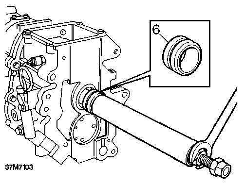
15. Fit output flange to output shaft.
16. Fit new’O’ring and spacer.
17. Fit new tab washer.
18. Fit output flange bolt and tighten to 90 Nm.
19. Lock bolt with tab washer.
6. Using LRT-37-015 and LRT-37-21 press on mainshaft oil seal collar.
3
37M7128
5. Apply Hylosil RTV 102 and fit extension case spool retainer, fit and tighten bolt to 8 Nm.

1. Remove all ’slave’ bolts from centre plate.
2. Refit oil filter.
3. Apply Hylosil RTV 102 to mating surfaces and fit extension housing. Ensure that oil pipe locates in filter and that roller bearings are not dislodged.
CAUTION: Do not use force. If necessary, remove extension housing and re-align oil pump drive.
4. Bolt extension housing to centre plate and main casing.
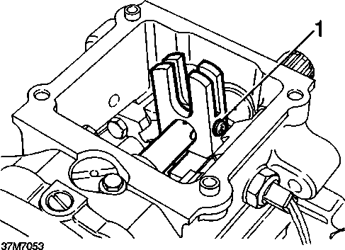
1. Position selector quadrant to selector shaft.
2. Apply Loctite 270 to thread of a new setscrew. Fit and tighten screw to 25 Nm.
3. Move selector shaft to neutral position.

CAUTION: Ensure end of setscrew locates in hole in selector shaft.

Gear change lever yoke - Type B gearbox - Refit Gear change lever yoke - Type D gearboxes -
- Refit


1. Position gear change lever yoke on selector shaft with ball facing towards output shaft.
2. Apply Loctite 270 to threads of a new setscrew, fit and tighten screw to 25 Nm.
CAUTION: Ensure end of setscrew locates in hole in selector shaft.
1. Position gear lever yoke on selector shaft with ball facing towards output shaft.
2. Apply Loctite 270 to threads of new setscrew. Fit and tighten screw to 25 Nm.
CAUTION: Ensure end of setscrew locates in hole in selector shaft.
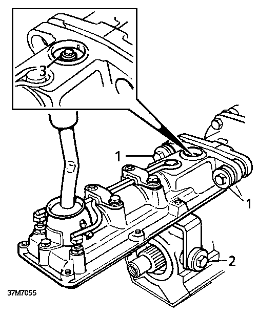
1. Apply Hylosil RTV 102 to mating surfaces and fit to extension housing.
2. Position remote housing to extension housing and gearcase ensuring rollers locate in quadrant.
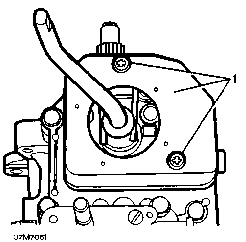
1. Smear a new gasket with grease and fit to remote housing.
2. Position gear change housing to remote housing ensuring gear lever ball is correctly located.
3. Fit but do not fully tighten 4 bolts.
4. Tighten remote housing, transfer box selector housing and gear change housing bolts to 25 Nm.
Transfer box selector housing - Type B gearbox -Refit
1. Smear a new gasket with grease and fit to gearcase.
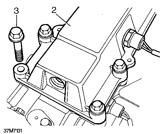
2. Position transfer box selector housing to gearcase, fit 4 bolts and tighten to 25 Nm
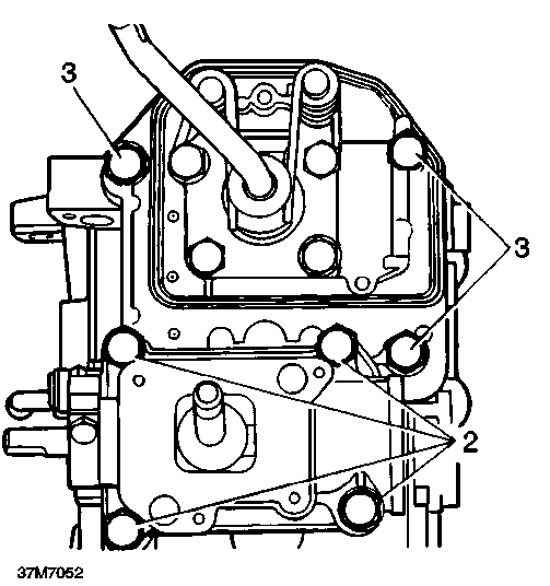
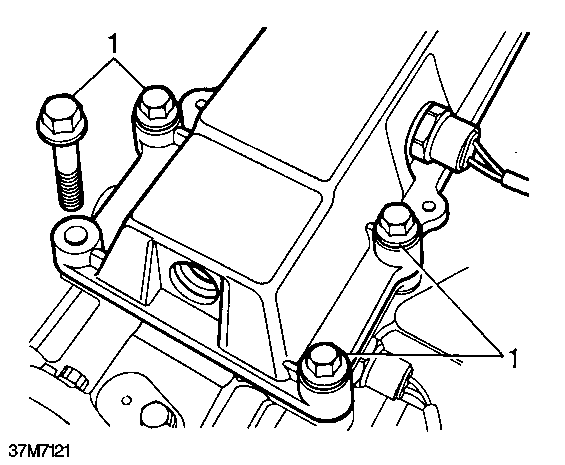
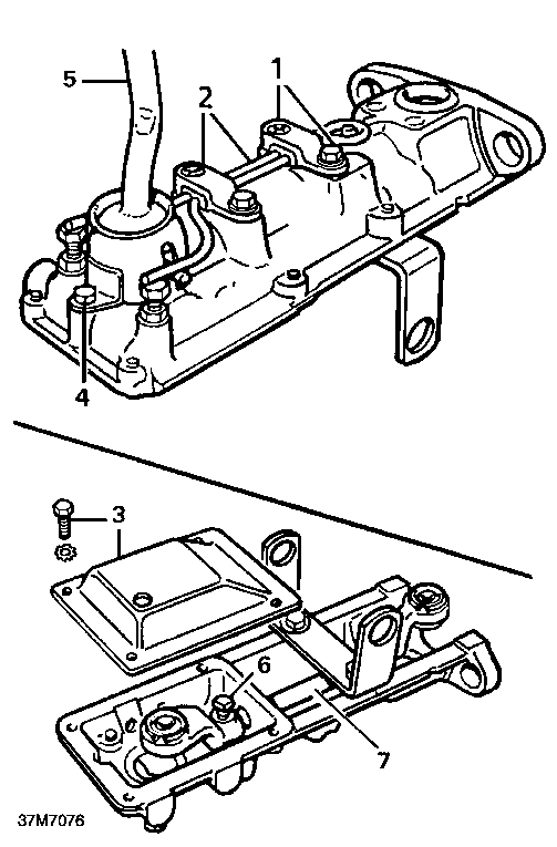
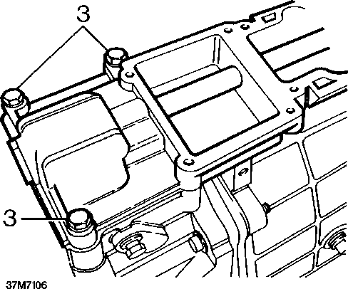
3. Fit but do not fully tighten 3 bolts in positions shown.
Transfer box selector housing - Type A gearbox -Refit
1. Smear a new gasket with grease and fit to remote housing.
2. Position transfer box selector housing to remote housing.
3. Fit but do not fully tighten 4 bolts.

Gear change housing - Type B gearbox - Refit Remote gear change - Type D gearbox - Refit

1. Apply Hylosil RTV 102 to mating surfaces of extension housing.
2. Position gear change housing to extension housing ensuring that gear lever passes through centre of gearchange lever yoke and engages in the gate plate.
3. Fit bolts and tighten to 25 Nm.
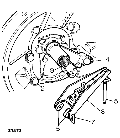
Remote gear change - Type C gearbox - Refit
1. Apply lithium based grease to selector rod yoke.
2. Position remote gear change to extension housing ensuring selector shaft pin is located in selector rod yoke.
3. Fit bolts, washers and mounting rubbers securing remote gear change to extension housing; do not tighten bolts at this stage.
4. Fit bolts, washers and mounting rubbers securing bracket to extension housing.
5. Tighten all bolts to 30 Nm.
1. Apply Hylosil RTV 102 to mating surfaces of extension housing and remote gearchange housing.
2. Position remote gear change housing on extension housing. Ensure that gear lever ball is correctly located.
3. Fit bolts and tighten to 25 Nm.
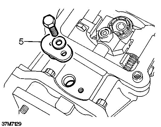
5th gear stop screw adjustment - Type A gearbox
1. Select reverse gear. While applying light pressure to gear lever towards left, turn screw clockwise until it contacts yoke.
2. Turn screw anti-clockwise until 25 mm free play is felt at knob, ensure 5th gear can be engaged.
3. Tighten locknut.
4. Check all other gears are selectable.
Bias spring adjustment - Type A gearbox Bias spring adjustment - Type B gearbox
~ NOTE: The purpose of this adjustment is / \ to set both bolts so that the bias spring legs apply equal pressure on both ends of the gear lever cross pin when third or fourth gear is engaged. This will ensure that when the lever is in neutral, the gear change mechanism is automatically aligned for third or fourth gear.
1. Slacken bias adjustment plate bolts. Select fourth gear and move lever fully to the right.
2. Tighten adjustment plate bolts.
3. Check adjustment is correct by selecting third and fourth gears.
1. Select third or fourth gear.
2. Adjust the two adjusting screws until both legs of the spring are approximately 0.5 mm clear of the cross pin in the gear lever.
3. Apply a light load to the gear lever in a left hand direction and adjust the right hand adjusting screw downward until the right hand spring leg just makes contact with the cross pin.
4. Repeat the same procedure for the left hand adjusting screw.
5. Lower both adjusting screws equal amounts until the radial play is just eliminated.
6. Tighten locknuts.
7. Return gear lever to neutral position and rock across the gate several times. The gear lever should return to the third and fourth gate.
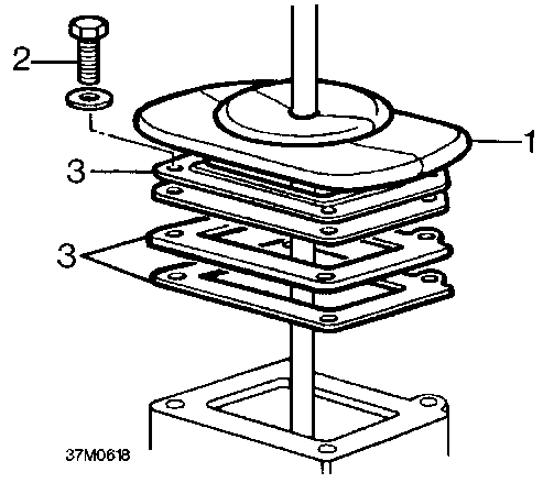
4. Fit sealing rubber to gear change housing, apply Hylogrip 640 to screws and fit cover.

Bias spring adjustment - Type C gearbox
~ NOTE: The purpose of this adjustment is / \ to ensure that when bias spring is correctly adjusted, the gear change mechanism is automatically aligned for 3rd or 4th gear selection when gear lever is in neutral.
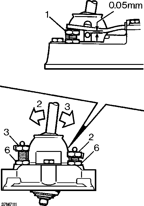
1. Adjust both bias spring adjustment bolts until a clearance of 0.05mm exists between both legs of bias spring and gear lever cross pin.
2. Apply a light load to move gear lever to the left and adjust right hand bolt until right hand leg of bias spring just contacts gear lever cross pin.
3. Move gear lever to the right and adjust left hand bolt.
4. Check that with gear lever moved fully to the left and right, spring legs just contact gear lever cross pin.
5. Select neutral then rock gear lever across the gate; when released, lever should return to 3rd/4th position.
6. Tighten adjusting bolt locknuts.
Clutch housing - Type A gearbox - Refit
1. Position clutch housing to gearbox.
2. Fit securing bolts.
^ NOTE: The 12 x 45mm bolts must be fitted / \ through locating dowels.
3. Tighten bolts by diagonal selection to 72 Nm.
4. Fit pivot post, fit and tighten bolts.
5. Apply lithium based grease to pivot post, pads and push rod.
6. Position pads to clutch release lever, fit release bearing.
7. Fit new clips to retain pads.
^ NOTE: Clips may become displaced in / \ service with no loss of performance.
8. Fit release lever.
9. Apply lithium based grease to splines of input shaft.
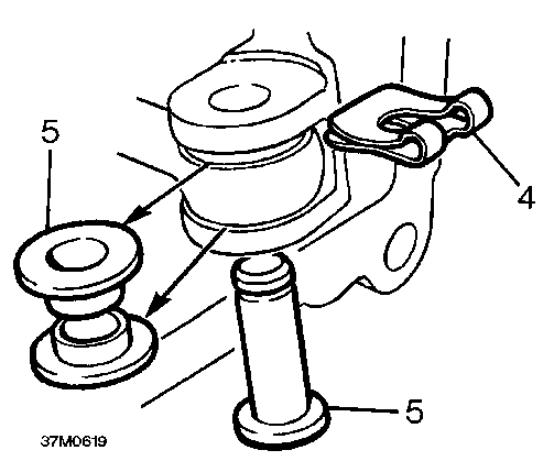
Clutch housing - Type B gearbox - Refit
37M0616
7. Position release lever to pivot post ensuring spring clip is located behind ’C’ clip; tighten bolt.
8. Fit clutch release bearing and retain using new clips.
^ NOTE: Clips may become displaced in / \ service with no loss of performance.
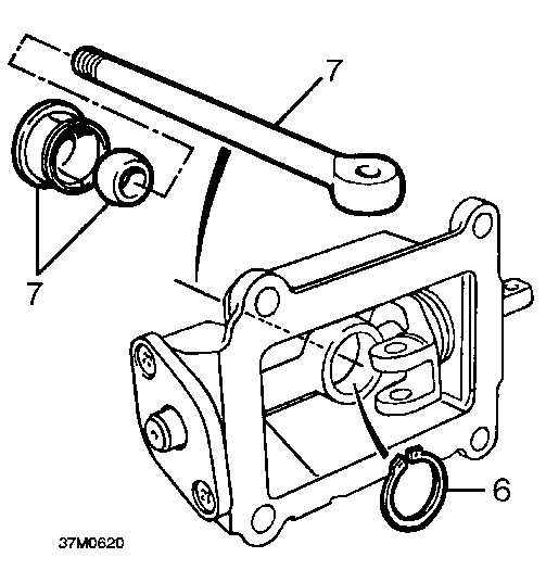
Clutch housing - Type C gearbox - Refit
1. Position clutch housing to gearbox.
2. Fit securing bolts.
^ NOTE: The 2 longest bolts must be fitted / \ at locating dowel positions.
3. Tighten bolts by diagonal selection to 72 Nm.
4. Apply lithium based grease to pivot post.
5. Fit release lever and clutch release bearing.
Adaptor housing - Type D gearbox - Refit
1. Position adaptor housing to gearbox.
2. Fit securing bolts.
^ NOTE: The two longest bolts must be / \ fitted at locating dowel positions.
3. Tighten bolts by diagonal selection to 72 Nm.
4. Apply lithium based grease to pivot post.
5. Fit pivot post and secure with two bolts.
1. Position clutch housing to gearbox.
2. Fit securing bolts.
^ NOTE: The 12 x 45mm bolts must be fitted / \ through locating dowels.
3. Tighten bolts by diagonal selection to 72 Nm.
4. Apply lithium based grease to pivot post, release lever, socket and push rod.
5. Fit a new ’C’ clip to pivot post, fit post.
6. Fit spring clip to release lever, fit but do not tighten bolt.